Cross-Org VPC Connectivity
Original report timestamp: September 1, 2026
Content review: September 12, 2026
This chapter compares five patterns for connecting accounts in different AWS Organizations, such as an existing environment and a separately governed GPU environment. The tables retain the measurements reported in the earlier document. This review checks AWS behavior and the arithmetic; it does not claim a new live deployment or independently reproduced benchmark.
Table of Contents
- Why Cross-Org Connectivity
- Comparing the Five Options
- Reported Verification Results
- Latency Measurements (M1–M7)
- Operational Findings
- Architecture Selection by Requirement
- Limitations and Next Checks
Why Cross-Org Connectivity
Contractual ownership, acquisitions, independent governance, or isolation requirements can place GPU workloads and existing services in different Organizations. Organization structure should follow those requirements, rather than an assumption that a second Organization automatically improves GPU discounts, quotas or compliance.
EC2 resource quotas are generally set for an account and Region; a separate account can provide that separation without requiring another Organization. Billing aggregation, negotiated discounts and duplicated governance also need review. An Organization boundary does not replace application authorization, network segmentation or audit controls.
For EKS, distinguish ordinary IP access to data pipelines/inference APIs from GPU collective communication. A CPU-instance request/response benchmark does not establish NCCL, throughput or RDMA performance. EFA OS-bypass traffic cannot cross VPCs or Availability Zones; normal IP traffic from its ENA interface remains routable.
Comparing the Five Options
The PrivateLink and Lattice columns describe the tested NLB-backed endpoint-service and HTTP-service patterns. PrivateLink also has resource and service-network endpoint types; Lattice also has TCP resource configurations. They are not universally “NLB required” or “L7 only” products.
| Aspect | ① TGW RAM Sharing | ② VPC Peering | ③ PrivateLink endpoint service | ④ TGW Peering | ⑤ VPC Lattice HTTP service |
|---|---|---|---|---|---|
| Mechanism | Share a TGW with the external account | Direct VPC pair | Consumer interface endpoint → provider NLB/service | Connect each owner's TGW | Associate services and client VPCs with a service network |
| Address overlap | Direct routing needs an unambiguous address plan | Overlapping CIDRs cannot be peered | Service access can handle overlapping VPC CIDRs | Direct routing needs an unambiguous address plan | Service access can handle overlapping VPC CIDRs |
| Connection model | Bidirectional IP routing when permitted | Bidirectional IP routing when permitted | Consumer initiates; responses can return on the connection | Bidirectional IP routing when permitted | Clients initiate requests to published services; reverse access needs its own configuration |
| Routing setup | VPC routes plus TGW tables/associations | Routes on both sides; no transitive VPC peering | Endpoint/service permissions and network controls, rather than general VPC transit | Explicit static routes toward the peer plus VPC routes | Service/network associations and policies, rather than general VPC transit |
| Control | TGW owner manages its TGW tables; consumers retain their VPC controls | Each VPC owner | Provider controls service permissions/targets; consumer controls its endpoints | Each TGW owner, with coordinated routes | Network/service owners and client-network controls |
| Original reported provisioning time | TGW ~3 min plus acceptance | Under 1 min | Endpoint ~3 min | ~7 min | ~5 min |
The provisioning times are observations from the original report, not SLAs or end-to-end delivery estimates. The routing row describes the two-TGW topology in this chapter; it does not assert unrestricted transit through arbitrary chains of peers. NAT or address redesign are additional approaches to overlap and require their own design.
Reported Verification Results
The original report states that all five patterns were established and traffic was exchanged across two Organizations. AWS documentation supports cross-account deployment of these patterns; a common Organization is not inherently required. However, IAM/SCP/sharing restrictions can block setup, and routes, security groups, NACLs, DNS and service authorization determine whether traffic works. Account IDs and acceptance alone are insufficient.
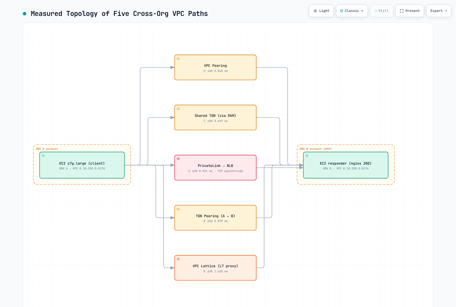
The figure preserves the original observations. Its Lattice value is HTTP KA, while the other displayed values are TCP_RR; they are not one directly comparable metric. The “GPU” label identifies the proposed environment, not a GPU benchmark.
Latency Measurements (M1–M7)
Reported setup: ap-northeast-2, matching ZoneId apne2-az1 across accounts, c7g.large, and one EC2 responder with nginx returning a fixed HTTP 200. The report describes three ENIs with per-path subnets/return routes, five round-robin interleaved rounds, 1,500 persistent TCP_RR samples per path, 100 ICMP samples per path, and 275 HTTP keep-alive samples per path.
The nginx description identifies the HTTP responder; the page does not identify the TCP_RR implementation or message sizes. Raw samples, software/kernel versions, timer boundaries and Linux return-path policy configuration are not linked here. Persistent connections aim to reduce repeated setup effects, but their timer boundaries cannot be independently checked from these tables.
All latency values below are milliseconds; TTL is a separate packet field. TCP_RR and ICMP are request/response round-trip measures. HTTP KA includes application processing. The two measurement campaigns below must be interpreted separately.
| ID | Path | ICMP p50 | TCP_RR p50 | RR p99 | RR sd | HTTP KA p50 | TTL |
|---|---|---|---|---|---|---|---|
| M1 | Same VPC → EC2 (baseline) | 0.121 | 0.049 | 0.062 | 0.007 | 0.087 | 127 |
| M2 | ② VPC Peering → EC2 | 0.125 | 0.048 | 0.057 | 0.011 | 0.080 | 127 |
| M3 | ① Shared TGW (RAM) → EC2 | 0.535 | 0.619 | 0.695 | 0.141 | 0.686 | 126 |
| M4 | ④ TGW Peering (two TGWs) → EC2 | 0.912 | 0.599 | 0.855 | 0.133 | 0.488 | 125 |
| M5 | ③ PrivateLink → NLB → EC2 | not measured | 0.961 | 1.084 | 0.035 | 0.711 | — |
| M6 | ⑤ VPC Lattice → EC2 target | not measured | not measured for this HTTP service | — | — | 1.635 | — |
| M7 | ② Peering → NLB → EC2 (NLB hop isolation) | not measured | 0.841 | 0.909 | 0.119 | 0.883 | — |
Differences Between Reported Medians
These are differences of path medians, not isolated one-way hop costs or measurements of an individual ENI/proxy component.
| Observed path comparison | Difference | Δ TCP_RR p50 | Δ ICMP p50 | Δ HTTP KA p50 |
|---|---|---|---|---|
| Peering vs same-VPC baseline | M2 − M1 | -0.001 | +0.004 | -0.007 |
| Shared TGW path vs peering | M3 − M2 | +0.571 | +0.410 | +0.606 |
| Two-TGW path vs peering | M4 − M2 | +0.551 | +0.787 | +0.408 |
| Peering with NLB vs direct peering | M7 − M2 | +0.793 | — | +0.803 |
| PrivateLink/NLB vs peering/NLB | M5 − M7 | +0.120 | — | -0.172 |
| Lattice HTTP service vs direct peering HTTP | M6 − M2 | — | — | +1.555 |
- M2 is close to the same-VPC baseline, but the tables do not establish statistical equivalence or zero overhead.
- The two-TGW path's TCP_RR median is lower than the single shared-TGW path's median. The data therefore do not support a universal “0.4–0.6 ms per TGW hop” or a linear hop-cost formula.
- M5−M7 is +0.120 ms for TCP_RR but −0.172 ms for HTTP KA. It cannot be labeled a pure PrivateLink ENI cost.
- The Lattice comparison is HTTP +1.555 ms, not TCP_RR. It describes this HTTP-service test, not every Lattice mode.
- TTL does not reveal the path's hop count without the initial TTL and relevant network behavior.
Separate Service-Fronted Campaign
The original report also placed NLBs on each L3 path. This is a useful comparison for that service-exposure pattern, not a requirement for every production Peering/TGW deployment.
| Configuration | TCP_RR p50 | HTTP KA p50 |
|---|---|---|
| ② Peering → NLB → EC2 | 0.622 | 0.648 |
| ③ PrivateLink → NLB → EC2 | 0.658 | 0.845 |
| ① Shared TGW → NLB → EC2 | 1.273 | 1.257 |
| ④ TGW Peering → NLB → EC2 | 1.425 | 1.279 |
| ⑤ Lattice HTTP service (no separate NLB in this test) | — | 1.680 |
In this campaign, PrivateLink/NLB minus Peering/NLB is +0.036 ms TCP_RR and +0.197 ms HTTP KA. The shared-TGW and peered-TGW TCP_RR medians are respectively 1.93× and 2.17× the PrivateLink median; the HTTP ratios are 1.49× and 1.51×. These are latency ratios, not throughput multipliers or proof that the paths are equivalent.
Lattice's HTTP median exceeds the shared-TGW/NLB and peered-TGW/NLB HTTP medians by +0.423 ms and +0.401 ms. Do not combine this campaign with the M1–M7 campaign to derive a component cost: even the Peering/NLB medians differ between runs.
The original report additionally describes a discarded burstable-instance/NLB→ALB/fresh-curl pilot with p95 around 7 ms, and first-flow increments of 0.6–1.6 ms. These remain attributed observations without linked raw samples, not AWS guarantees. Measure connection establishment and steady-state behavior separately for the actual application.
Operational Findings
- RAM external sharing: external principals must be allowed and the outside-Organization account must accept the share invitation. The
CreateResourceShareAPI'sallowExternalPrincipalsdefault is true; explicitly setting--allow-external-principalsdocuments intent, but omitting that literal CLI flag is not universally a failure cause. Verify the effective share configuration and permissions. - Shared TGW VPC attachment acceptance: with
AutoAcceptSharedAttachmentsdisabled (the default), the TGW owner must accept the shared attachment. Enabling it changes that workflow. RAM share acceptance and TGW attachment acceptance are different steps. Consumers cannot modify the owner's TGW route tables, but still control their own VPC routes and security settings. - TGW peering acceptance: the accepter TGW owner accepts the pending peering request in the accepter Region, even for same-account peering. Use that request's
TransitGatewayAttachmentId; do not confuse it with a TGW ID or VPC-attachment ID. ANotFoundresponse does not establish a rule that the two sides require different IDs. The original report's roughly two-minute visibility delay is an observation, not a fixed wait guarantee. - Peering routes: direct TGW-to-TGW peering uses explicitly configured static routes, not BGP route propagation across the peering attachment. Configure the relevant TGW and VPC route tables in both directions. Automation can manage these static routes.
- Route priority: longest-prefix matching comes first. A static route wins over a propagated route for the same destination prefix; a less-specific static route does not override a more-specific propagated route.
- Lattice target security groups: for the documented VPC-association service path, use the Region/IP-family managed prefix lists (
com.amazonaws.REGION.vpc-latticeandcom.amazonaws.REGION.ipv6.vpc-lattice) on the actual target and health-check ports. The original169.254.171.0/24example is not a universal list definition; managed lists can include link-local or non-routable public addresses. Endpoint/resource-gateway paths have their own controls. IAM service authentication must also be configured; it is not enabled merely by associating a VPC. - Cleanup ownership: the original report describes GuardDuty-managed networking dependencies, IAM policy attachments and remaining Lattice resources affecting teardown. Inspect the actual dependency IDs and owning service before acting. Do not disable managed security controls or delete unrelated resources simply to force a VPC/role deletion.
Architecture Selection by Requirement
| Requirement | Candidate pattern | Checks that matter |
|---|---|---|
| Each Organization must retain its own TGW routing authority | ④ TGW Peering | Static-route coordination, address plan, throughput, availability, inspection and transfer charges |
| A small set of inference/service endpoints should be exposed | ③ PrivateLink endpoint service | Supported protocol/model, endpoint acceptance, application auth, DNS, cost and actual payload/concurrency |
| Service access across overlapping CIDRs | ③ PrivateLink or ⑤ Lattice | Service/resource scope; evaluate NAT/address redesign if broader IP routing is required |
| Another account can use a centrally controlled hub | ① TGW RAM Sharing | External share policy, acceptance settings and the owner's TGW control model |
| A small number of direct VPC pairs | ② VPC Peering | Non-overlapping CIDRs, pairwise route maintenance, quotas and data-transfer charges |
| Managed HTTP service identity/discovery/governance is required | ⑤ VPC Lattice | Explicit IAM auth policies, signed requests, service connectivity and workload measurements |
A hybrid of TGW peering and PrivateLink may fit independent network governance plus limited API exposure. The published latency tables do not establish that it is optimal for most GPU environments. Choose based on the required connectivity and controls, then measure the actual workload.
Limitations and Next Checks
The original report excludes measured Network Firewall inspection paths, cross-Region latency, and throughput/concurrency. It reports functional overlap checks without publishing overlap latency results. GPU collectives, EFA/RDMA, representative payload sizes, uncertainty estimates and full reproduction artifacts are also not established by this page.
Keep the reported numbers as historical context. Before deployment, validate the target accounts' policies and supported connection model, required bidirectional routes or service access, failure behavior and the application's latency/throughput budget. This review performed no AWS provisioning or live benchmark.
References
- Scalable multi-VPC networking whitepaper
- Cross-account TGW sharing
- Single or multiple Organizations
- RAM CreateResourceShare API
- TGW acceptance options
- TGW peering acceptance
- TGW routing and evaluation order
- PrivateLink endpoint types
- Private NAT and overlapping networks
- Lattice security groups
- EC2 account/Region quotas
- EFA limitations
- VPC Lattice guide
- Cross-Org quiz