ネットワーク構成
< 前へ: 前提条件 | 目次 | 次へ: Air-Gap セットアップ >
サポートされるバージョン: EKS 1.31+, nodeadm 0.1+ 最終更新: February 23, 2026
このドキュメントでは、EKS Hybrid Nodes に必要なネットワーク構成について説明します。CIDR 要件、ファイアウォールルール、AWS エンドポイントアクセス、セキュリティグループ構成、DNS セットアップを含みます。
ネットワークアーキテクチャ概要
次の図は、VPC 構成、Transit Gateway ルーティング、リモート CIDR、ファイアウォールルールを含む、EKS Hybrid Nodes の完全なネットワークトポロジーを示しています。
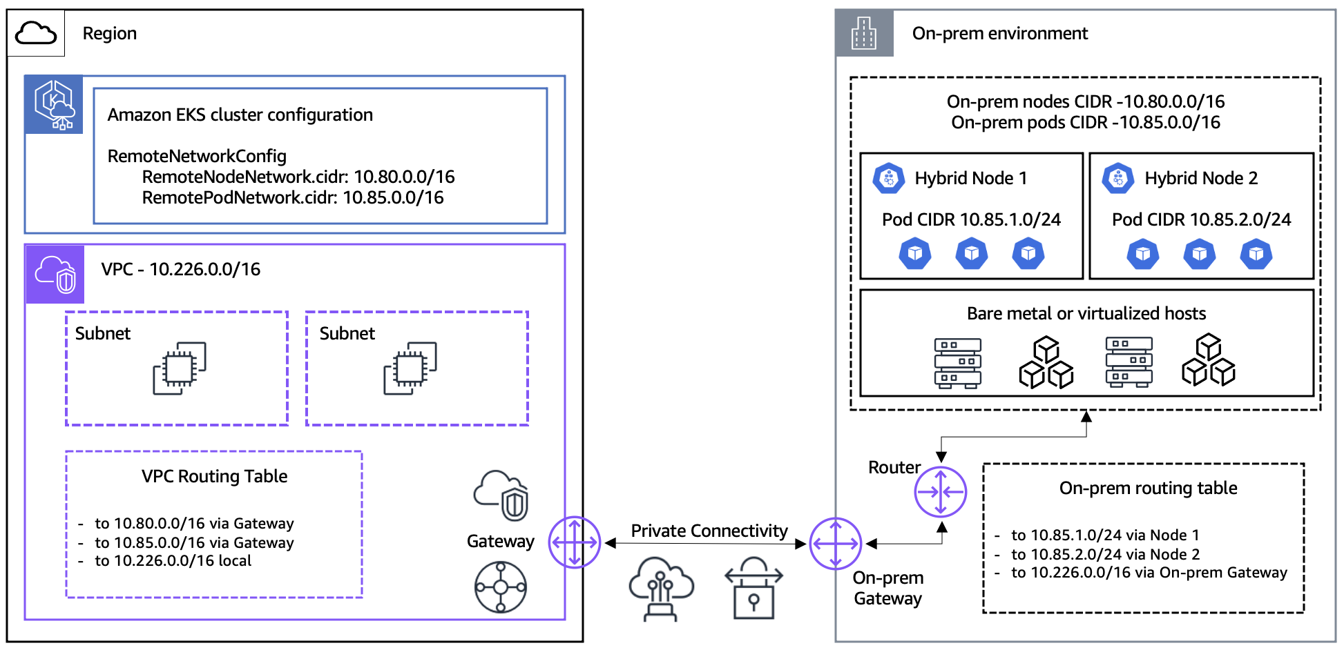
ネットワークハブとしての VPC
EKS Hybrid Nodes 環境では、VPC は hybrid nodes と control plane の間の network hub として機能します。
- ENI の配置: EKS control plane は VPC サブネットに ENI (Elastic Network Interface) を配置します。これらの ENI は、control plane と hybrid nodes の間の通信エンドポイントです。
- トラフィックパス: control plane と hybrid nodes の間のすべてのトラフィックは、これらの ENI を経由します。API server リクエスト、kubelet 通信、webhook 呼び出し、およびすべての control plane トラフィックは VPC ENI を通過します。
- ENI IP の変更: クラスター更新時 (例: バージョンアップグレード) に ENI が削除され再作成される場合があり、その IP アドレスが変わることがあります。ファイアウォールルールで個別 IP の代わりにサブネット CIDR 範囲を使用すると、これらの変更に柔軟に対応できます。
┌─────────────────────────────────────────────────────────────────┐
│                         AWS Cloud                                │
│  ┌──────────────────┐    ┌──────────────────────────────────┐   │
│  │  EKS Control     │    │              VPC                  │   │
│  │     Plane        │◄──►│  ┌────────┐  ┌────────┐          │   │
│  │                  │    │  │  ENI   │  │  ENI   │          │   │
│  └──────────────────┘    │  │10.0.1.x│  │10.0.2.x│          │   │
│                          │  └────┬───┘  └────┬───┘          │   │
│                          └───────┼───────────┼──────────────┘   │
└──────────────────────────────────┼───────────┼──────────────────┘
                                   │           │
                           VPN / Direct Connect
                                   │           │
┌──────────────────────────────────┼───────────┼──────────────────┐
│                          On-Premises                             │
│                    ┌─────────────┴───────────┴─────────────┐    │
│                    │         Hybrid Nodes                   │    │
│                    │   ┌─────────┐    ┌─────────┐          │    │
│                    │   │  Node   │    │  Node   │          │    │
│                    │   │ kubelet │    │ kubelet │          │    │
│                    │   └─────────┘    └─────────┘          │    │
│                    └───────────────────────────────────────┘    │
└─────────────────────────────────────────────────────────────────┘
CIDR 範囲の要件
オンプレミスの node と pod の CIDR は、次の要件を満たす必要があります。
- RFC-1918 範囲 内である必要があります:
10.0.0.0/8,172.16.0.0/12,192.168.0.0/16 - 次と 重複してはいけません:
- 相互 (node CIDR と pod CIDR)
- EKS クラスターの VPC CIDR
- Kubernetes service IPv4 CIDR
EKS クラスターの作成時に RemoteNodeNetwork と RemotePodNetwork フィールドを指定します。
ルーティング可能な Pod ネットワークとルーティング不可の Pod ネットワーク
| Configuration | Routable (Recommended) | Unroutable |
|---|---|---|
| Setup | BGP (recommended), static routes, or custom routing | CNI egress masquerade/NAT |
| Webhooks | Can run on hybrid nodes | Must run on cloud nodes only |
| Pod↔Pod communication | Direct cloud↔on-premises communication | Not possible |
| AWS service integration | ALB, Prometheus, etc. can reach hybrid workloads | Cannot reach hybrid workloads |
推奨事項: Pod CIDR をルーティング可能にするには Cilium BGP Control Plane を使用してください。
必須ファイアウォールポート
クラスター通信ポート
オンプレミスと AWS 間の通信のために、次のポートを開く必要があります。
| Port | Protocol | Direction | Purpose |
|---|---|---|---|
| 443 | TCP | On-Prem → AWS | Kubelet to Kubernetes API server |
| 443 | TCP | On-Prem → AWS | Pods to Kubernetes API server |
| 10250 | TCP | AWS → On-Prem | API server to kubelet |
| Webhook ports | TCP | AWS → On-Prem | API server to webhooks (routable pod networks only) |
| 53 | TCP/UDP | Bidirectional | CoreDNS (pod CIDR ↔ pod CIDR; include VPC CIDR if CoreDNS runs in cloud) |
| App ports | User-defined | Bidirectional | Pod-to-pod application communication |
VPN ポート (Site-to-Site VPN を使用する場合)
| Port | Protocol | Direction | Purpose |
|---|---|---|---|
| 500 | UDP | Bidirectional | IKE (Internet Key Exchange) |
| 4500 | UDP | Bidirectional | IPSec NAT-T |
Cilium CNI ポート
CNI として Cilium を使用する場合に必要な追加ポート:
| Port | Protocol | Direction | Purpose |
|---|---|---|---|
| 8472 | UDP | Bidirectional | VXLAN overlay (default tunnel mode) |
| 4240 | TCP | Bidirectional | Health check |
注記: Cilium と Calico の詳細なファイアウォール要件については、各プロジェクトの公式ドキュメントを参照してください。
iptables ルール例
# Allow Kubernetes API server communication
sudo iptables -A INPUT -p tcp --dport 443 -s 10.0.0.0/8 -j ACCEPT
sudo iptables -A OUTPUT -p tcp --dport 443 -d 10.0.0.0/8 -j ACCEPT

# Allow Kubelet API
sudo iptables -A INPUT -p tcp --dport 10250 -s 10.0.0.0/8 -j ACCEPT

# Allow Cilium VXLAN
sudo iptables -A INPUT -p udp --dport 8472 -j ACCEPT
sudo iptables -A OUTPUT -p udp --dport 8472 -j ACCEPT

# Allow Cilium health check
sudo iptables -A INPUT -p tcp --dport 4240 -j ACCEPT
sudo iptables -A OUTPUT -p tcp --dport 4240 -j ACCEPT

# Allow DNS
sudo iptables -A INPUT -p tcp --dport 53 -j ACCEPT
sudo iptables -A INPUT -p udp --dport 53 -j ACCEPT
sudo iptables -A OUTPUT -p tcp --dport 53 -j ACCEPT
sudo iptables -A OUTPUT -p udp --dport 53 -j ACCEPT

# Save rules
sudo iptables-save | sudo tee /etc/iptables/rules.v4
オンプレミスのアウトバウンドアクセス要件
インストールとアップグレードに必要なエンドポイント
nodeadm のインストールおよびアップグレード中、オンプレミスノードから HTTPS (443) 経由で次の AWS エンドポイントに到達できる必要があります。
| Component | URL | Notes |
|---|---|---|
| EKS node artifacts (S3) | https://hybrid-assets.eks.amazonaws.com | nodeadm binary and dependencies |
| EKS service | https://eks.<region>.amazonaws.com | Cluster information lookup |
| ECR service | https://api.ecr.<region>.amazonaws.com | Container image pulls |
| SSM binary | https://amazon-ssm-<region>.s3.<region>.amazonaws.com | When using SSM credential provider |
| SSM service | https://ssm.<region>.amazonaws.com | When using SSM credential provider |
| IAM Roles Anywhere | https://rolesanywhere.<region>.amazonaws.com | When using IAM RA credential provider |
| OS package manager | Regional-specific endpoints | System package installation |
継続的な運用に必要なエンドポイント
| Purpose | Source | Destination | Notes |
|---|---|---|---|
| Kubelet → API server | Node CIDR | EKS cluster IPs | Port 443 |
| Pod → API server | Pod CIDR | EKS cluster IPs | Port 443 |
| SSM credential refresh | Node CIDR | SSM endpoint | 5-minute heartbeat interval |
| IAM RA credential refresh | Node CIDR | IAM Anywhere endpoint | Periodic refresh |
| EKS Pod Identity | Node CIDR | EKS Auth endpoint | When using Pod Identity |
EKS クラスター Network Interface IP の検出
ファイアウォールルールで EKS クラスター IP が必要な場合は、次のコマンドを使用します。
aws ec2 describe-network-interfaces \
  --filters "Name=vpc-id,Values=<VPC_ID>" "Name=description,Values=Amazon EKS*" \
  --query 'NetworkInterfaces[].PrivateIpAddress' \
--output text注記: EKS network interface はクラスター更新時 (例: バージョンアップグレード) に削除され再作成される場合があります。制約されたサブネットサイズを使用すると IP 範囲が予測しやすくなり、ファイアウォール構成が簡単になります。
VPC Private Endpoints (Air-Gap / Private Connectivity)
オンプレミスノードがインターネットアクセスなしで VPN または Direct Connect 経由で AWS に接続する場合、AWS services にプライベートに到達するために VPC Interface Endpoints (PrivateLink) を構成する必要があります。
VPC Endpoints が必要な理由
標準の AWS API 呼び出しはパブリックインターネットを通過します。air-gapped または private-only 環境ではインターネット経路がないため、AWS services に到達できません。VPC Interface Endpoints は VPC 内にプライベート IP アドレスを持つ ENI (Elastic Network Interface) を作成し、オンプレミスノードが VPN/Direct Connect 経由で AWS API に直接到達できるようにします。
On-premises node
  → VPN / Direct Connect
    → VPC Interface Endpoint ENI (private IP)
→ AWS Service (EKS, ECR, STS, SSM, etc.)重要ポイント: Gateway endpoints (S3 および DynamoDB 用) は VPC route table にルートを追加するだけで、VPN/Direct Connect 経由の オンプレミスネットワークからは到達できません。オンプレミスから S3 にアクセスするには、Interface type の S3 endpoint を使用する必要があります。
必須 Interface VPC Endpoints
| Service | Endpoint Service Name | Private DNS | Purpose |
|---|---|---|---|
| EKS | com.amazonaws.<region>.eks | Yes | Kubernetes API server communication |
| EKS Auth | com.amazonaws.<region>.eks-auth | Yes | Pod Identity authentication |
| ECR API | com.amazonaws.<region>.ecr.api | Yes | Image metadata queries |
| ECR DKR | com.amazonaws.<region>.ecr.dkr | Yes | Image pull (Docker registry) |
| S3 | com.amazonaws.<region>.s3 | — | Image layers, nodeadm artifacts (Interface type) |
| STS | com.amazonaws.<region>.sts | Yes | IAM credential exchange |
| SSM | com.amazonaws.<region>.ssm | Yes | When using SSM credential provider |
| SSM Messages | com.amazonaws.<region>.ssmmessages | Yes | SSM Session Manager communication |
注記: S3 Interface endpoints は
private_dns_enabledを自動的にはサポートしません。S3 ドメインの private DNS 解決が必要な場合は、別途 Private Hosted Zone (PHZ) を構成する必要があります。hybrid-assets.eks.amazonaws.comのプライベートミラーリングパターンについては、Air-Gap Setup - hybrid-assets Private Mirroring を参照してください。
Terraform による VPC Endpoints の作成
Security Group
resource "aws_security_group" "vpc_endpoints" {
  name_prefix = "vpc-endpoints-"
  vpc_id      = var.vpc_id
  description = "Security group for VPC Interface Endpoints"

  ingress {
    description = "HTTPS from VPC and on-premises"
    from_port   = 443
    to_port     = 443
    protocol    = "tcp"
    cidr_blocks = [
      var.vpc_cidr,           # VPC internal traffic
      var.remote_node_cidr,   # On-premises node CIDR
      var.remote_pod_cidr     # On-premises pod CIDR
    ]
  }

  egress {
    from_port   = 0
    to_port     = 0
    protocol    = "-1"
    cidr_blocks = ["0.0.0.0/0"]
  }

  tags = {
    Name = "vpc-endpoints-sg"
  }
}
Interface VPC Endpoints
# List of Interface endpoints to create
locals {
  interface_endpoints = {
    eks          = "com.amazonaws.${var.region}.eks"
    eks-auth     = "com.amazonaws.${var.region}.eks-auth"
    ecr-api      = "com.amazonaws.${var.region}.ecr.api"
    ecr-dkr      = "com.amazonaws.${var.region}.ecr.dkr"
    sts          = "com.amazonaws.${var.region}.sts"
    ssm          = "com.amazonaws.${var.region}.ssm"
    ssmmessages  = "com.amazonaws.${var.region}.ssmmessages"
  }
}

resource "aws_vpc_endpoint" "interface" {
  for_each = local.interface_endpoints

  vpc_id              = var.vpc_id
  service_name        = each.value
  vpc_endpoint_type   = "Interface"
  private_dns_enabled = true

  subnet_ids         = var.private_subnet_ids
  security_group_ids = [aws_security_group.vpc_endpoints.id]

  tags = {
    Name = "vpce-${each.key}"
  }
}

# S3 Interface endpoint (Interface type, not Gateway)
resource "aws_vpc_endpoint" "s3_interface" {
  vpc_id              = var.vpc_id
  service_name        = "com.amazonaws.${var.region}.s3"
  vpc_endpoint_type   = "Interface"
  private_dns_enabled = false  # S3 does not support auto Private DNS for Interface type

  subnet_ids         = var.private_subnet_ids
  security_group_ids = [aws_security_group.vpc_endpoints.id]

  tags = {
    Name = "vpce-s3-interface"
  }
}
AWS CLI による VPC Endpoints の作成
# 1. Create security group for VPC endpoints
SG_ID=$(aws ec2 create-security-group \
  --group-name vpc-endpoints-sg \
  --description "Security group for VPC Interface Endpoints" \
  --vpc-id <VPC_ID> \
  --query 'GroupId' --output text)

# Allow port 443 inbound
aws ec2 authorize-security-group-ingress \
  --group-id $SG_ID \
  --ip-permissions '[
    {"IpProtocol": "tcp", "FromPort": 443, "ToPort": 443,
     "IpRanges": [
       {"CidrIp": "<VPC_CIDR>", "Description": "VPC internal"},
       {"CidrIp": "<REMOTE_NODE_CIDR>", "Description": "On-prem nodes"},
       {"CidrIp": "<REMOTE_POD_CIDR>", "Description": "On-prem pods"}
     ]}
  ]'

# 2. Create Interface VPC endpoint (EKS example)
aws ec2 create-vpc-endpoint \
  --vpc-id <VPC_ID> \
  --vpc-endpoint-type Interface \
  --service-name com.amazonaws.<REGION>.eks \
  --subnet-ids <SUBNET_ID_1> <SUBNET_ID_2> \
  --security-group-ids $SG_ID \
  --private-dns-enabled

# 3. Create remaining service endpoints
for SERVICE in eks-auth ecr.api ecr.dkr sts ssm ssmmessages; do
  echo "Creating endpoint for: $SERVICE"
  aws ec2 create-vpc-endpoint \
    --vpc-id <VPC_ID> \
    --vpc-endpoint-type Interface \
    --service-name com.amazonaws.<REGION>.$SERVICE \
    --subnet-ids <SUBNET_ID_1> <SUBNET_ID_2> \
    --security-group-ids $SG_ID \
    --private-dns-enabled
done

# 4. S3 Interface endpoint (without private-dns-enabled)
aws ec2 create-vpc-endpoint \
  --vpc-id <VPC_ID> \
  --vpc-endpoint-type Interface \
  --service-name com.amazonaws.<REGION>.s3 \
  --subnet-ids <SUBNET_ID_1> <SUBNET_ID_2> \
  --security-group-ids $SG_ID

# 5. Verify created endpoints
aws ec2 describe-vpc-endpoints \
  --filters "Name=vpc-id,Values=<VPC_ID>" \
  --query 'VpcEndpoints[].{ID:VpcEndpointId, Service:ServiceName, State:State}' \
  --output table
オンプレミス DNS 解決フロー
VPC endpoints の private_dns_enabled オプションは VPC 内でのみ機能します。オンプレミスノードが AWS service ドメイン (例: eks.ap-northeast-2.amazonaws.com) を VPC endpoint のプライベート IP に解決するには、Route 53 Resolver Inbound Endpoint 経由で DNS クエリをルーティングする必要があります。
On-premises node
  → On-premises DNS server (conditional forwarding)
    → Route 53 Resolver Inbound Endpoint (in VPC)
      → Route 53 resolves via Private Hosted Zone / VPC DNS
        → Returns VPC Endpoint ENI private IP
          → On-premises node reaches ENI directly over VPN/DX
オンプレミス DNS での Conditional Forwarding の構成
オンプレミス DNS サーバー (例: BIND, Windows DNS, dnsmasq) が AWS ドメインを Route 53 Inbound Endpoint に転送するように構成します。
# BIND example (/etc/named.conf)
zone "amazonaws.com" {
    type forward;
    forward only;
    forwarders {
        10.0.1.10;    # Route 53 Inbound Endpoint IP #1
        10.0.2.10;    # Route 53 Inbound Endpoint IP #2
    };
};

zone "eks.amazonaws.com" {
    type forward;
    forward only;
    forwarders {
        10.0.1.10;
        10.0.2.10;
    };
};注記: Route 53 Resolver Inbound Endpoint の作成については、このドキュメントの DNS Configuration セクションを参照してください。VPC endpoints を構成した後は、
nslookup eks.<region>.amazonaws.comでプライベート IP が返されることを必ず確認してください。
AWS Security Group 構成
EKS はクラスター作成時に security group のインバウンドルールを自動的に構成しますが、アウトバウンドルールは自動作成されません (security group はデフォルトですべてのアウトバウンドを許可します)。
自動作成されるインバウンドルール
| Protocol | Port | Source | Purpose |
|---|---|---|---|
| TCP | 443 | Remote node CIDR(s) | Kubelet to Kubernetes API |
| TCP | 443 | Remote pod CIDR(s) | Pods to Kubernetes API (non-NAT CNI) |
手動で追加するアウトバウンドルール
| Protocol | Port | Destination | Purpose |
|---|---|---|---|
| TCP | 10250 | Remote node CIDR(s) | API server to kubelet |
| TCP | Webhook ports | Remote pod CIDR(s) | API server to webhooks |
# Example: Create a custom security group
aws ec2 create-security-group \
  --group-name hybrid-nodes-sg \
  --description "Security group for EKS Hybrid Nodes" \
  --vpc-id <VPC_ID>

# Add inbound rules
aws ec2 authorize-security-group-ingress \
  --group-id <SG_ID> \
  --ip-permissions '[
    {"IpProtocol": "tcp", "FromPort": 443, "ToPort": 443,
     "IpRanges": [{"CidrIp": "<REMOTE_NODE_CIDR>"}, {"CidrIp": "<REMOTE_POD_CIDR>"}]}
]'注意: デフォルトの上限は security group あたり 60 個のインバウンドルールです。また、リモートネットワークが削除されても EKS はルールを自動的には削除しないため、手動クリーンアップが必要です。
Pod CIDR ファイアウォール戦略
Pod-to-Pod 通信のために、Pod CIDR 範囲全体に対するファイアウォールルールを登録する必要があります。
# Pod CIDR range example: 10.244.0.0/16
# Check cluster's Pod CIDR
kubectl cluster-info dump | grep -m 1 cluster-cidr

# Add firewall rules for Pod CIDR
sudo iptables -A INPUT -s 10.244.0.0/16 -j ACCEPT
sudo iptables -A OUTPUT -d 10.244.0.0/16 -j ACCEPT
sudo iptables -A FORWARD -s 10.244.0.0/16 -j ACCEPT
sudo iptables -A FORWARD -d 10.244.0.0/16 -j ACCEPT

# Add Service CIDR as well (e.g., 172.20.0.0/16)
sudo iptables -A INPUT -s 172.20.0.0/16 -j ACCEPT
sudo iptables -A OUTPUT -d 172.20.0.0/16 -j ACCEPT
DNS 構成
Route 53 Resolver Inbound Endpoint
オンプレミスが AWS ドメインを照会できるようにするため、Inbound Endpoint を作成します。
# Create Inbound Endpoint
aws route53resolver create-resolver-endpoint \
  --creator-request-id "hybrid-inbound-$(date +%s)" \
  --name "hybrid-inbound-endpoint" \
  --security-group-ids sg-0123456789abcdef0 \
  --direction INBOUND \
  --ip-addresses SubnetId=subnet-111111111,Ip=10.0.1.10 SubnetId=subnet-222222222,Ip=10.0.2.10

# Check Endpoint IPs
aws route53resolver list-resolver-endpoint-ip-addresses \
  --resolver-endpoint-id rslvr-in-xxxxxxxxxxxxx
Route 53 Resolver Outbound Endpoint
AWS がオンプレミスドメインを照会できるようにするため、Outbound Endpoint と転送ルールを作成します。
# Create Outbound Endpoint
aws route53resolver create-resolver-endpoint \
  --creator-request-id "hybrid-outbound-$(date +%s)" \
  --name "hybrid-outbound-endpoint" \
  --security-group-ids sg-0123456789abcdef0 \
  --direction OUTBOUND \
  --ip-addresses SubnetId=subnet-111111111 SubnetId=subnet-222222222

# Create forwarding rule (on-premises domain)
aws route53resolver create-resolver-rule \
  --creator-request-id "forward-onprem-$(date +%s)" \
  --name "forward-to-onprem" \
  --rule-type FORWARD \
  --domain-name "internal.company.io" \
  --resolver-endpoint-id rslvr-out-xxxxxxxxxxxxx \
  --target-ips "Ip=192.168.1.10,Port=53" "Ip=192.168.1.11,Port=53"

# Associate rule with VPC
aws route53resolver associate-resolver-rule \
  --resolver-rule-id rslvr-rr-xxxxxxxxxxxxx \
  --vpc-id vpc-0123456789abcdef0
CoreDNS カスタムドメイン構成
オンプレミスドメインへの DNS クエリをオンプレミス DNS サーバーへ転送します。
apiVersion: v1
kind: ConfigMap
metadata:
  name: coredns
  namespace: kube-system
data:
  Corefile: |
    .:53 {
        errors
        health {
            lameduck 5s
        }
        ready
        kubernetes cluster.local in-addr.arpa ip6.arpa {
            pods insecure
            fallthrough in-addr.arpa ip6.arpa
        }
        prometheus :9153
        forward . /etc/resolv.conf {
            max_concurrent 1000
        }
        cache 30
        loop
        reload
        loadbalance
    }
    internal.company.io:53 {
        errors
        cache 30
        forward . 192.168.1.10 192.168.1.11 {
            max_concurrent 1000
        }
}# Apply CoreDNS ConfigMap
kubectl apply -f coredns-configmap.yaml
# Restart CoreDNS
kubectl rollout restart deployment coredns -n kube-system
# Test DNS resolution
kubectl run dns-test --rm -it --image=busybox --restart=Never -- nslookup internal.company.ioCoreDNS Dual-Location Deployment (On-Premises + Cloud)
Dual-Location Deployment が必要な理由
EKS Hybrid Nodes 環境で CoreDNS が cloud nodes のみに実行されている場合、オンプレミス Pods からの DNS クエリは VPN/Direct Connect リンクを通って cloud へ行き、戻ってくる必要があります。逆に、CoreDNS がオンプレミスノードのみに実行されている場合、cloud Pods からの DNS クエリは逆方向の往復を行う必要があります。
DNS レイテンシを最小化し、片側でネットワーク障害が発生しても DNS service の可用性を維持するために、CoreDNS Pods は両側に存在する必要があります。
推奨 Replica 数
最小 4 replicas (cloud 2 + on-premises 2) が推奨されます。各ロケーションに少なくとも 2 replicas を配置することで、高可用性を確保できます。
CoreDNS Deployment パッチ
topologySpreadConstraints と tolerations を使用して、cloud nodes とオンプレミスノード全体に CoreDNS Pods を均等に分散します。
apiVersion: apps/v1
kind: Deployment
metadata:
  name: coredns
  namespace: kube-system
spec:
  replicas: 4
  template:
    spec:
      tolerations:
        - key: "eks.amazonaws.com/compute-type"
          value: "hybrid"
          effect: "NoSchedule"
      topologySpreadConstraints:
        - maxSkew: 1
          topologyKey: "eks.amazonaws.com/compute-type"
          whenUnsatisfiable: ScheduleAnyway
          labelSelector:
            matchLabels:
              k8s-app: kube-dns
kubectl patch コマンド
kubectl patch deployment coredns -n kube-system --type=strategic -p '{
  "spec": {
    "replicas": 4,
    "template": {
      "spec": {
        "tolerations": [
          {
            "key": "eks.amazonaws.com/compute-type",
            "value": "hybrid",
            "effect": "NoSchedule"
          }
        ],
        "topologySpreadConstraints": [
          {
            "maxSkew": 1,
            "topologyKey": "eks.amazonaws.com/compute-type",
            "whenUnsatisfiable": "ScheduleAnyway",
            "labelSelector": {
              "matchLabels": {
                "k8s-app": "kube-dns"
              }
            }
          }
        ]
      }
    }
  }
}'
配置の確認
# Verify CoreDNS Pods are distributed across both node types
kubectl get pods -n kube-system -l k8s-app=kube-dns -o wide

# Check compute-type labels on nodes
kubectl get nodes -L eks.amazonaws.com/compute-type注記:
- EKS managed CoreDNS add-on を使用する場合、同じ構成を add-on の
configurationValuesから適用できます。whenUnsatisfiable: ScheduleAnywayを使用すると、ノードが片側にしか存在しない場合でもスケジューリングがブロックされません。これにより、初期クラスター bootstrap 時に CoreDNS が正常に起動することが保証されます。
トラフィックフローパターン
AWS とオンプレミス間のトラフィックフローパターンを理解することは、ファイアウォール構成とトラブルシューティングにとって重要です。次のセクションでは、公式 AWS アーキテクチャ図を用いて各トラフィックパターンを詳しく説明します。
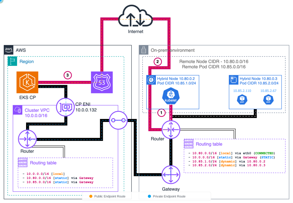
Pattern 1: Kubelet → EKS Control Plane
Kubelet は DNS lookup を介して API server endpoint へ HTTPS リクエストを開始します。public access mode では、トラフィックはパブリックインターネットを通過します。private mode では、トラフィックは VPN/DX を通じて VPC ENI へ流れます。
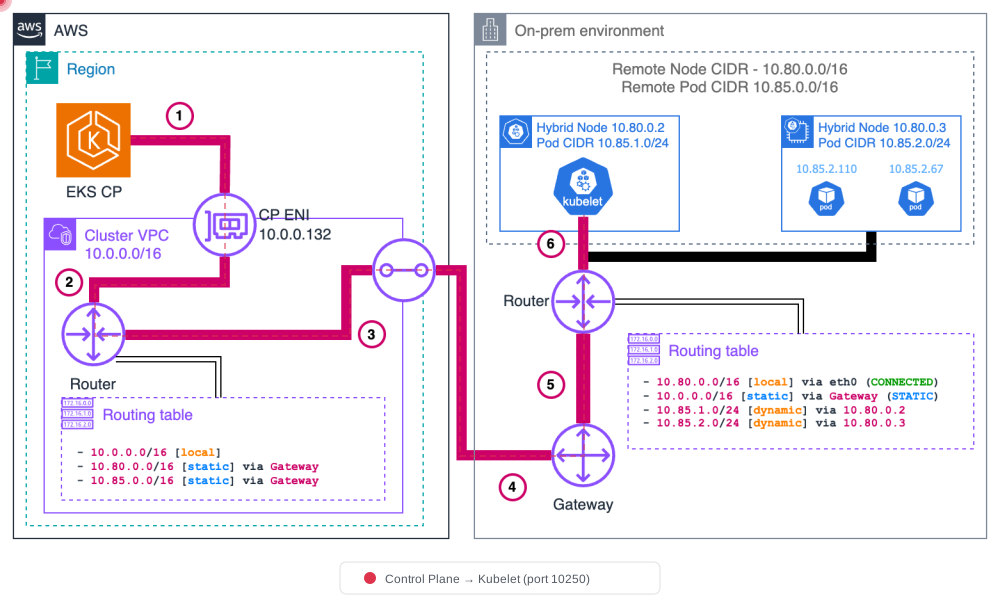
Pattern 2: EKS Control Plane → Kubelet
API server は node status object から node IP を取得します。トラフィックは VPC を通ってルーティングされ、その後 Direct Connect または VPN 経由で cloud boundary を越えて、ポート 10250 の kubelet に到達します。これは kubectl logs, kubectl exec, kubectl port-forward などで使用されます。
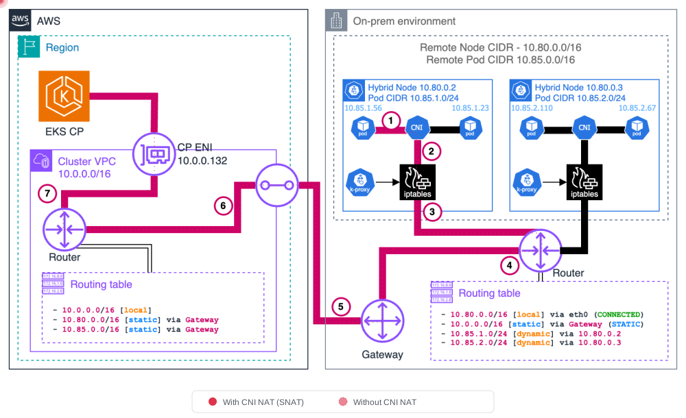
Pattern 3: Pod → EKS Control Plane
Pods は kubernetes Service (ClusterIP) を介して Kubernetes API と通信します。kube-proxy は DNAT を適用して service IP を control plane ENI IP に変換し、その後パケットは VPN/DX を経由して VPC へルーティングされます。
- CNI NAT なし: Pod は kubernetes service IP (例: 172.16.0.1) に送信し、kube-proxy が DNAT を適用して control plane ENI IP に変換します。戻りトラフィックには pod CIDR 経由の逆方向ルーティングが必要です。
- CNI NAT あり: CNI は node 処理の前に SNAT を適用し、戻りルーティングを簡素化します (追加の pod CIDR ルーティングは不要です)。
Pattern 4: EKS Control Plane → Pod (Webhooks)
API server は hybrid nodes 上で実行されている webhook pods への直接接続を開始します。トラフィックは remote pod CIDR 用に VPC を通ってルーティングされ、gateway 経由で境界を越えます。これには ルーティング可能な pod CIDR が必要です。
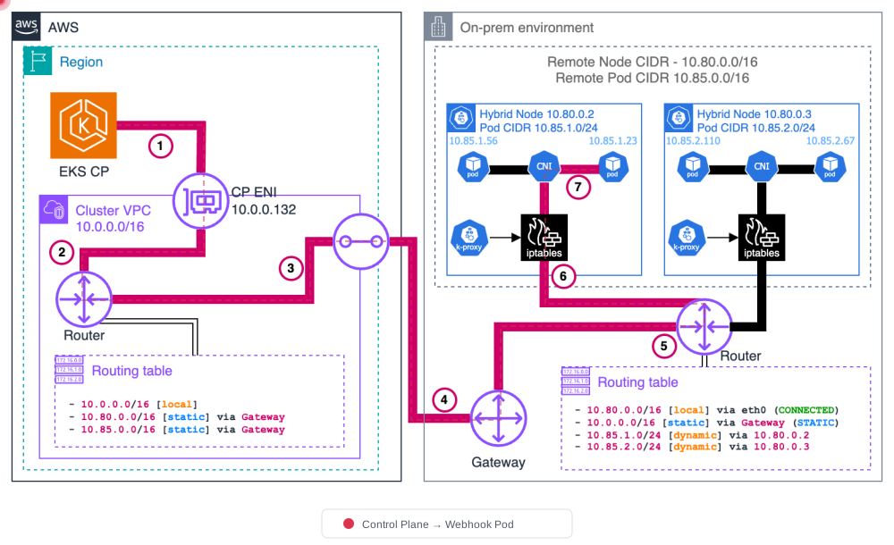
重要: オンプレミス pod CIDR がルーティング可能でない場合、すべての webhooks を cloud nodes で実行する必要があります。以下の Webhook Configuration を参照してください。
Pattern 5: Pod ↔ Pod on Hybrid Nodes
異なる hybrid nodes 上の Pods は、VXLAN encapsulation (または Geneve、IP-in-IP のような類似の overlay protocols) を使用して通信します。CNI は、送信元/宛先 node IP を使用する outer headers で元の pod-to-pod パケットをカプセル化します。受信側ノードの CNI はデカプセル化し、宛先 pod に配信します。
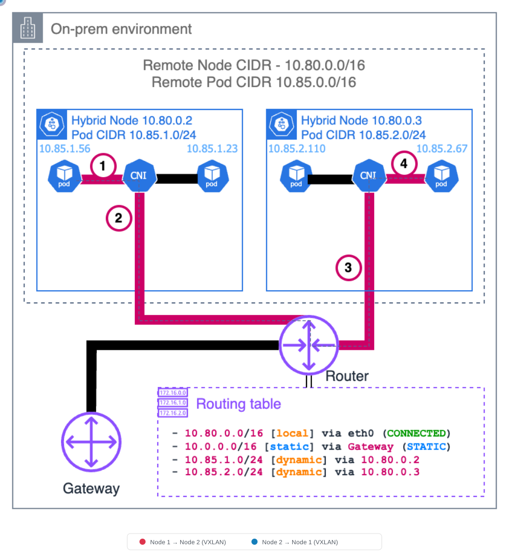
VXLAN カプセル化の詳細
VXLAN (Virtual Extensible LAN) は L2 フレームを L3 パケットにカプセル化し、overlay network を作成します。hybrid nodes 間の Pod 通信でパケット構造がどのように変換されるかを以下に示します。
元のパケット (カプセル化前)
┌────────────────────────────────────────────────┐
│  Pod-A IP (src) → Pod-B IP (dst) │   Payload   │
│    10.85.0.10       10.85.1.20   │   (data)    │
└────────────────────────────────────────────────┘
VXLAN カプセル化後
┌──────────────────────────────────────────────────────────────────────────────┐
│ Outer IP Header │ UDP Header │ VXLAN Header │      Original Packet          │
│ Node-A → Node-B │ Port 8472  │    (VNI)     │ Pod-A IP → Pod-B IP │ Payload │
│ 10.80.1.10      │            │              │ 10.85.0.10  10.85.1.20        │
│   → 10.80.1.11  │            │              │                               │
└──────────────────────────────────────────────────────────────────────────────┘
カプセル化プロセス (送信元 Node)
- Pod-A が Pod-B にパケットを送信します
- 送信元 node の CNI (Cilium) が宛先 Pod IP を検索し、ターゲット node を特定します
- CNI は元のパケットを VXLAN header と outer IP header で包みます
- outer header は node IP を送信元/宛先として使用します
- カプセル化されたパケットは UDP ポート 8472 経由で送信されます
デカプセル化プロセス (宛先 Node)
- 宛先 node が UDP ポート 8472 で VXLAN パケットを受信します
- CNI は VXLAN header と outer IP header を取り除きます
- 元のパケットが宛先 Pod に配信されます
主要コンポーネント
| Component | Description |
|---|---|
| VNI (VXLAN Network Identifier) | 24-bit identifier that isolates pod network traffic (default: auto-assigned) |
| UDP Port | Cilium default: 8472, Standard VXLAN: 4789 |
| MTU | Must account for VXLAN overhead (50 bytes), e.g., 1500 → 1450 |
注記: VXLAN 以外にも、Cilium は Geneve や IP-in-IP などの他の tunnel protocols をサポートしています。tunnel mode を選択するには
--tunnelオプションを使用します。
Pattern 6: Cloud Pod ↔ Hybrid Pod (East-West)
VPC pods (VPC CNI を使用) は hybrid pods に直接送信します。VPC ルーティングはトラフィックをオンプレミス gateway へ向けます。パケットは境界を越え、hybrid node に到達します。これには ルーティング可能な pod CIDR と適切な VPC route table エントリが必要です。
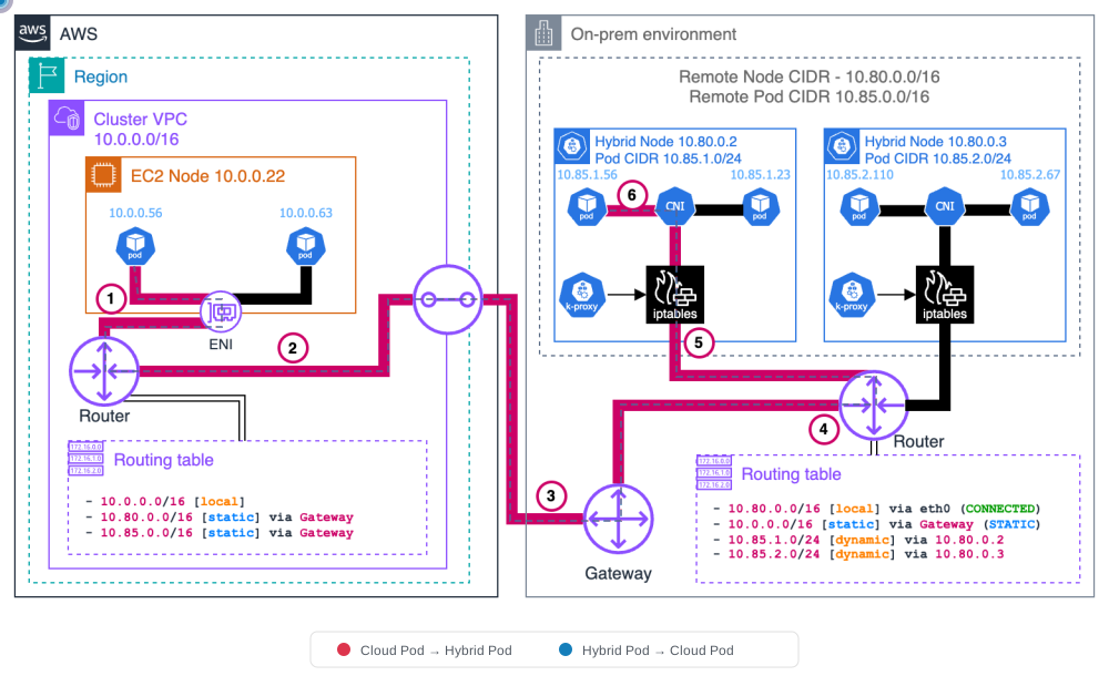
トラフィックフローサマリー
| # | Flow | Direction | Port | Requirements |
|---|---|---|---|---|
| 1 | Kubelet → API Server | On-Prem → AWS | TCP 443 | VPN/DX or internet |
| 2 | API Server → Kubelet | AWS → On-Prem | TCP 10250 | SG outbound rule |
| 3 | Pod → API Server | On-Prem → AWS | TCP 443 | kube-proxy DNAT |
| 4 | API Server → Webhook Pod | AWS → On-Prem | TCP 8443+ | Routable pod CIDR |
| 5 | Hybrid Pod ↔ Hybrid Pod | On-Prem internal | UDP 8472 | Cilium VXLAN |
| 6 | Cloud Pod ↔ Hybrid Pod | AWS ↔ On-Prem | VPC route | Routable pod CIDR + VPC routes |
kube-proxy iptables Chain 構造
kube-proxy は iptables ルールを使用して Kubernetes Service トラフィックを実際の Pods にルーティングします。同じ 3 層 chain 構造が hybrid nodes にも適用されます。
KUBE-SERVICES (entry point)
  └─→ KUBE-SVC-xxxx (per-service chain, load balancing)
        └─→ KUBE-SEP-xxxx (per-endpoint chain, DNAT to pod IP)
Chain の役割
| Chain | Role | Example |
|---|---|---|
| KUBE-SERVICES | Matches destination IP:Port against all ClusterIP services | 172.20.0.1:443 → KUBE-SVC-NPX... |
| KUBE-SVC-xxxx | Selects endpoint using probability-based load balancing | 3 Pods → 33% probability each |
| KUBE-SEP-xxxx | Performs DNAT to specific Pod IP:Port | DNAT to 10.85.0.15:8080 |
実際の iptables ルール例
# KUBE-SERVICES chain (nat table)
-A KUBE-SERVICES -d 172.20.0.10/32 -p tcp -m tcp --dport 80 -j KUBE-SVC-XXXXXX

# KUBE-SVC chain (load balancing)
-A KUBE-SVC-XXXXXX -m statistic --mode random --probability 0.33333 -j KUBE-SEP-AAAAAA
-A KUBE-SVC-XXXXXX -m statistic --mode random --probability 0.50000 -j KUBE-SEP-BBBBBB
-A KUBE-SVC-XXXXXX -j KUBE-SEP-CCCCCC

# KUBE-SEP chain (DNAT)
-A KUBE-SEP-AAAAAA -p tcp -j DNAT --to-destination 10.85.0.15:8080
-A KUBE-SEP-BBBBBB -p tcp -j DNAT --to-destination 10.85.0.16:8080
-A KUBE-SEP-CCCCCC -p tcp -j DNAT --to-destination 10.85.1.20:8080
Hybrid Environment への影響: 上の例で
10.85.1.20が別の hybrid node 上の Pod である場合、DNAT 後のパケットは VXLAN でカプセル化され、その node に送信されます。kube-proxy は Service トラフィックを Pod IP に変換し、CNI が実際のネットワークルーティングを処理します。
kubelet エンドポイント
kubelet は各 node 上で実行され、API server 通信用の REST endpoints を公開します。
kubelet API ポートとエンドポイント
| Port | Endpoint | Purpose |
|---|---|---|
| 10250 | /pods | List pods running on the node |
| 10250 | /exec/{namespace}/{pod}/{container} | Execute commands in containers (kubectl exec) |
| 10250 | /logs/{namespace}/{pod}/{container} | Stream container logs (kubectl logs) |
| 10250 | /metrics | Expose kubelet metrics (for Prometheus scraping) |
| 10250 | /healthz | kubelet health check |
Node 登録と Address レポート
kubelet が node をクラスターに登録すると、Node.status.addresses に address 情報を報告します。
status:
  addresses:
  - address: 10.80.1.10        # Actual on-premises IP
    type: InternalIP
  - address: hybrid-node-001   # Node hostname
type: Hostname- InternalIP: node の実際のオンプレミス IP アドレスです。API server はこのアドレスを使用して kubelet に接続します。
- Hostname: node の hostname です。
ファイアウォールルール要件: API server は
InternalIPを使用して kubelet に接続するため、TCP ポート 10250 を AWS → On-Prem 方向で開く必要があります。この接続がブロックされると、kubectl exec,kubectl logs,kubectl port-forwardなどのコマンドは失敗します。
ルーティング可能な Pod CIDR 構成
オンプレミスの pod CIDR をルーティング可能にすることは、webhooks、east-west traffic、および AWS service integration (ALB, Prometheus など) に不可欠です。
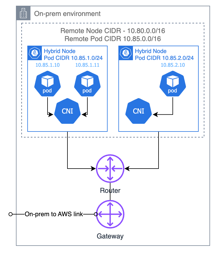
Option 1: BGP (Recommended)
CNI は仮想ルーターとして動作し、ノードごとの pod CIDR ルートをローカルのオンプレミスルーターに伝播します。これは最も動的で保守しやすいアプローチです。
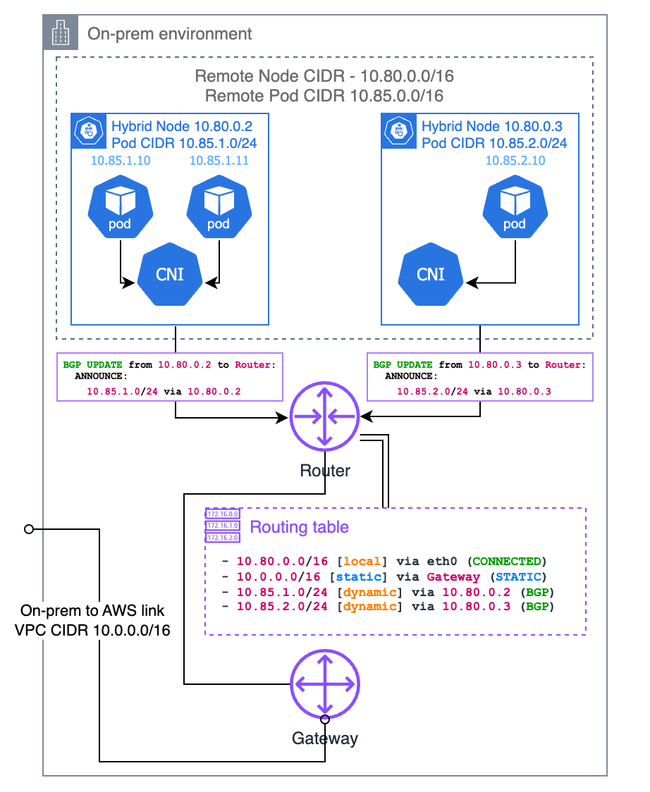
Cilium BGP Control Plane 構成
apiVersion: cilium.io/v2alpha1
kind: CiliumBGPClusterConfig
metadata:
  name: hybrid-bgp-config
spec:
  bgpInstances:
  - name: hybrid-instance
    localASN: 65001
    peers:
    - name: on-prem-router
      peerASN: 65000
      peerAddress: 10.80.0.1
      peerConfigRef:
        name: on-prem-peer
---
apiVersion: cilium.io/v2alpha1
kind: CiliumBGPPeerConfig
metadata:
  name: on-prem-peer
spec:
  families:
  - afi: ipv4
    safi: unicast
  gracefulRestart:
    enabled: true
---
apiVersion: cilium.io/v2alpha1
kind: CiliumBGPAdvertisement
metadata:
  name: pod-cidr-advert
spec:
  advertisements:
  - advertisementType: PodCIDR
  - advertisementType: Service
    service:
      addresses:
      - ClusterIP
ASN (Autonomous System Number) の理解
上記の Cilium BGP 構成では、localASN と peerASN は Autonomous System Numbers、つまり各 BGP 参加者に割り当てられる一意の識別子です。すべての BGP speaker (ルーター、スイッチ、またはこの場合は各 node 上の Cilium) は ASN を持つ必要があり、接続先の peer も ASN を持つ必要があります。
Private ASN Range と Public ASN Range
| Range | Type | Use Case |
|---|---|---|
| 64512 – 65534 | 16-bit Private | Internal networks, data centers, lab environments. Use this range for EKS Hybrid Nodes. |
| 4200000000 – 4294967294 | 32-bit Private | Large-scale internal deployments needing many unique ASNs |
| 1 – 64511 | 16-bit Public | Internet-facing networks registered with RIR (ARIN, RIPE, APNIC) |
EKS Hybrid Nodes の場合: 常に private ASN ranges (64512–65534) を使用してください。public ASN は不要です。ここでの BGP は、Cilium nodes とオンプレミスルーター間の内部ネットワーク内でのみ使用されます。
ASN 値の選び方
localASN(例:65001): hybrid nodes 上で実行される Cilium に割り当てる ASN です。同じクラスター内のすべての Cilium nodes は通常、1 つの ASN を共有します。peerASN(例:65000): Cilium が peer するオンプレミスルーターの ASN です。この値を確認するには、ルーターの BGP 構成を確認してください。
環境に BGP がまだ構成されていない場合は、private range から異なる 2 つの数値を選ぶだけで構いません (例: ルーターに 65000、Cilium に 65001)。ネットワークチームがすでに内部で BGP を使用している場合は、ASN の競合を避けるために調整してください。
オンプレミスルーター BGP 構成例
以下は、上記の Cilium 構成に一致するように BGP peering の ルーター側 を構成する例です。各例では、ルーターは ASN 65000 を使用し、10.80.1.10 の Cilium node (ASN 65001) と peer します。
Cisco IOS / IOS-XE
router bgp 65000
 neighbor 10.80.1.10 remote-as 65001
 neighbor 10.80.1.10 description "EKS Hybrid Node - Cilium BGP"
 !
 address-family ipv4 unicast
  neighbor 10.80.1.10 activate
  neighbor 10.80.1.10 soft-reconfiguration inbound
 exit-address-family
Cisco NX-OS (Nexus)
router bgp 65000
  address-family ipv4 unicast
  neighbor 10.80.1.10
    remote-as 65001
    description EKS-Hybrid-Cilium
    address-family ipv4 unicast
      soft-reconfiguration inbound
Juniper Junos (MX / QFX / SRX)
set protocols bgp group eks-hybrid type external
set protocols bgp group eks-hybrid peer-as 65001
set protocols bgp group eks-hybrid neighbor 10.80.1.10 description "EKS Hybrid Node"
set protocols bgp group eks-hybrid family inet unicast
set routing-options autonomous-system 65000
Arista EOS
router bgp 65000
   neighbor 10.80.1.10 remote-as 65001
   neighbor 10.80.1.10 description EKS-Hybrid-Cilium
   !
   address-family ipv4
      neighbor 10.80.1.10 activate
MikroTik RouterOS
/routing bgp connection
add name=eks-hybrid remote.address=10.80.1.10 remote.as=65001 \
    local.role=ebgp as=65000 address-families=ip
FRRouting (FRR) — Software Router (Linux)
FRRouting は、Linux servers や VMs 上の software BGP router として一般的に使用されます。
router bgp 65000
 neighbor 10.80.1.10 remote-as 65001
 neighbor 10.80.1.10 description EKS-Hybrid-Cilium
 !
 address-family ipv4 unicast
  neighbor 10.80.1.10 activate
 exit-address-family
AWS Transit Gateway (TGW)
AWS Transit Gateway を Site-to-Site VPN とともに使用する場合、TGW 側 ASN は TGW 作成時に構成されます。
# TGW creation with custom ASN
aws ec2 create-transit-gateway \
  --options AmazonSideAsn=65000

# The VPN tunnel automatically establishes BGP with the TGW ASN
# On-premises router (or Cilium) uses its own ASN to peer with TGW注記: AWS TGW のデフォルト ASN は
64512です。Cilium nodes が65001を使用する場合、Cilium config の TGW (または VGW) peer ASN は TGW の ASN と一致する必要があります。
複数の Hybrid Nodes
複数の hybrid nodes がある場合、各 node は同じ localASN で独自の Cilium BGP speaker を実行します。オンプレミスルーターは各 node と個別に peer します。
# Router config — peer with each hybrid node
router bgp 65000
 neighbor 10.80.1.10 remote-as 65001   ! hybrid-node-001
 neighbor 10.80.1.11 remote-as 65001   ! hybrid-node-002
 neighbor 10.80.1.12 remote-as 65001   ! hybrid-node-003
各 node は自身の pod CIDR slice (例: node-001 は 10.85.0.0/25、node-002 は 10.85.0.128/25 を広告) を広告するため、ルーターはすべての pod CIDR に対する完全な routing table を構築します。
BGP Peering の確認
cilium bgp peers
cilium bgp routes
Hybrid nodes では Session State が established と表示される必要があります。
Option 2: Static Routes
pod CIDR を使った手動ルーター構成です。最も簡単ですがエラーが起こりやすく、node が変更されると手動更新が必要です。
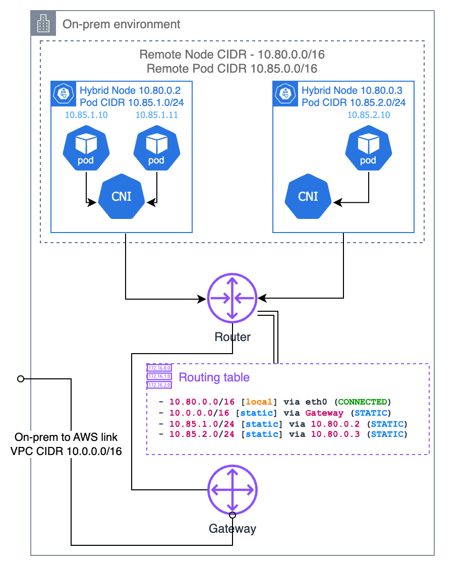
Cluster-Pool IPAM 割り当ての理解
Cilium の cluster-pool IPAM mode では、pod CIDR pool 全体が node ごとの固定サイズのブロックに分割されます。04-node-bootstrap.md の Cilium values で、2 つの主要パラメーターが構成されます。
| Parameter | Example Value | Description |
|---|---|---|
clusterPoolIPv4PodCIDRList | 10.85.0.0/16 | The entire pod CIDR pool |
clusterPoolIPv4MaskSize | 25 | Subnet size allocated per node (/25 = 128 IPs) |
たとえば、pool が 10.85.0.0/16、mask size が /25 の場合、最大 512 nodes にそれぞれ 128 個の pod IP を割り当てることができます。Cilium Operator は node 登録順にブロックを割り当てます。
| Node | Allocated PodCIDR | Available Pod IPs |
|---|---|---|
| hybrid-node-001 | 10.85.0.0/25 | 10.85.0.1 – 10.85.0.126 |
| hybrid-node-002 | 10.85.0.128/25 | 10.85.0.129 – 10.85.0.254 |
| hybrid-node-003 | 10.85.1.0/25 | 10.85.1.1 – 10.85.1.126 |
重要: この割り当て情報は CiliumNode CR に記録されます。Kubernetes Node object の
spec.podCIDRとは異なる場合があるため、static routes を構成する際は必ず CiliumNode CR を参照してください。
Node ごとの PodCIDR の照会
static routes を構成するには、各 node に割り当てられた PodCIDR と node IP (next hop) を特定する必要があります。照会方法は CNI によって異なります。
Cilium — CiliumNode CR の spec.ipam.podCIDRs が authoritative source です。
kubectl get ciliumnodes -o custom-columns='\
NAME:.metadata.name,\
NODE_IP:.spec.addresses[0].ip,\
POD_CIDR:.spec.ipam.podCIDRs[0]'
NAME NODE_IP POD_CIDR
hybrid-node-001 10.80.1.10 10.85.0.0/25
hybrid-node-002 10.80.1.11 10.85.0.128/25
hybrid-node-003 10.80.1.12 10.85.1.0/25CiliumNode CR の構造、スクリプトでの使用方法、詳細については、Cilium IPAM — Querying Per-Node PodCIDRs via CiliumNode CR を参照してください。
Calico — BlockAffinity CR は node ごとの CIDR ブロックを追跡します。
kubectl get blockaffinities -o custom-columns='\
NAME:.metadata.name,\
CIDR:.spec.cidr,\
NODE:.spec.node'
⚠ 非推奨: Calico は EKS Hybrid Nodes で公式にはサポートされなくなりました。新規デプロイメントには Cilium を使用してください。詳細な BlockAffinity のクエリについては、Calico Advanced Topics — Querying Per-Node PodCIDRs via BlockAffinity を参照してください。
Static Routes の構成
CiliumNode (または Calico BlockAffinity) CR から得た情報に基づき、ルーターに static routes を追加します。一般的なパターンは次のとおりです。
Destination = Node's PodCIDR
Next Hop    = Node's InternalIP
Linux (ip route)
# Add routes for each node's pod CIDR
ip route add 10.85.0.0/25 via 10.80.1.10    # hybrid-node-001
ip route add 10.85.0.128/25 via 10.80.1.11  # hybrid-node-002
ip route add 10.85.1.0/25 via 10.80.1.12    # hybrid-node-003
再起動後も永続化するには:
# /etc/network/interfaces.d/hybrid-routes (Debian/Ubuntu)
up ip route add 10.85.0.0/25 via 10.80.1.10
up ip route add 10.85.0.128/25 via 10.80.1.11
up ip route add 10.85.1.0/25 via 10.80.1.12

# Or for NetworkManager (RHEL/Rocky)
# /etc/NetworkManager/dispatcher.d/99-hybrid-routes
Cisco IOS / IOS-XE
ip route 10.85.0.0 255.255.255.128 10.80.1.10 name hybrid-node-001-pods
ip route 10.85.0.128 255.255.255.128 10.80.1.11 name hybrid-node-002-pods
ip route 10.85.1.0 255.255.255.128 10.80.1.12 name hybrid-node-003-pods
FRRouting (FRR)
ip route 10.85.0.0/25 10.80.1.10
ip route 10.85.0.128/25 10.80.1.11
ip route 10.85.1.0/25 10.80.1.12
AWS VPC Route Table
VPN/Direct Connect で接続された AWS VPC から pods に到達する必要がある場合は、aggregate CIDR を使用します。
# Add VPC route with aggregate CIDR (VPN Gateway or TGW as next hop)
aws ec2 create-route \
  --route-table-id rtb-0123456789abcdef0 \
  --destination-cidr-block 10.85.0.0/16 \
--gateway-id vgw-0123456789abcdef0# Terraform
resource "aws_route" "hybrid_pod_cidr" {
route_table_id = aws_route_table.main.id
destination_cidr_block = "10.85.0.0/16"
gateway_id = aws_vpn_gateway.main.id
}自動化と BGP との比較
CiliumNode CR から ip route コマンドを自動生成するスクリプト例:
#!/bin/bash
# generate-static-routes.sh — Generate static route commands from CiliumNode CRs
kubectl get ciliumnodes -o json | jq -r \
  '.items[] | "ip route add \(.spec.ipam.podCIDRs[0]) via \(.spec.addresses[0].ip)"'
出力例:
ip route add 10.85.0.0/25 via 10.80.1.10
ip route add 10.85.0.128/25 via 10.80.1.11
ip route add 10.85.1.0/25 via 10.80.1.12
Static Routes と BGP の比較
| Aspect | Static Routes | BGP (Option 1) |
|---|---|---|
| Node addition | Manual route addition to router required | Routes propagated automatically |
| Node removal | Manual route deletion from router required | Routes withdrawn automatically |
| Node IP change | All routes must be manually updated | Updates propagated automatically |
| Failure detection | None (stale routes remain) | Auto-detected via BGP keepalives |
| Configuration complexity | Low | Medium (BGP peering setup required) |
| Scalability | Suitable for 1–5 nodes | Scales to tens/hundreds of nodes |
推奨事項:
- PoC / 小規模環境 (1–5 nodes): Static routes はクイックスタートに適しています
- 本番 / 5+ nodes: BGP (Option 1) を使用してください。node の変更に自動的に対応し、運用負荷を大幅に削減します
- ポリシーにより BGP が許可されない環境: 上記の自動化スクリプトと static routes を使用して route changes を管理します
Option 3: ARP Proxying
Nodes はホストしている pod IP に対する ARP リクエストに応答します。ローカルルーターへの Layer 2 network proximity が必要です。Cilium には proxy ARP サポートが組み込まれています。ルーターの BGP または static route 構成は不要ですが、pod CIDR は他のネットワークと重複してはいけません。
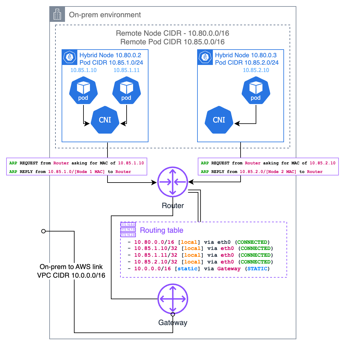
Network Policies
Network policies は、hybrid node 環境で Pod-to-Pod トラフィックを制御するために使用できます。Cilium CNI を使用する場合、標準の Kubernetes NetworkPolicy と拡張された CiliumNetworkPolicy の両方がサポートされます。
Kubernetes NetworkPolicy
標準の Kubernetes NetworkPolicy は、基本的な L3/L4 トラフィックフィルタリングを提供します。
apiVersion: networking.k8s.io/v1
kind: NetworkPolicy
metadata:
  name: allow-frontend-to-backend
  namespace: bookinfo
spec:
  podSelector:
    matchLabels:
      app: reviews
  policyTypes:
  - Ingress
  ingress:
  - from:
    - podSelector:
        matchLabels:
          app: productpage
    ports:
    - protocol: TCP
      port: 9080
この policy は、bookinfo namespace 内で app: productpage ラベルを持つ Pods のみが、app: reviews Pods のポート 9080 にアクセスすることを許可します。
CiliumNetworkPolicy
CiliumNetworkPolicy は、L7 filtering、DNS-aware policies、identity-based matching によって Kubernetes NetworkPolicy を拡張します。
apiVersion: cilium.io/v2
kind: CiliumNetworkPolicy
metadata:
  name: allow-frontend-to-backend
  namespace: bookinfo
spec:
  endpointSelector:
    matchLabels:
      app: reviews
  ingress:
  - fromEndpoints:
    - matchLabels:
        app: productpage
    toPorts:
    - ports:
      - port: "9080"
        protocol: TCP
CiliumNetworkPolicy の高度な機能
L7 HTTP Filtering
apiVersion: cilium.io/v2
kind: CiliumNetworkPolicy
metadata:
  name: l7-rule
  namespace: bookinfo
spec:
  endpointSelector:
    matchLabels:
      app: reviews
  ingress:
  - fromEndpoints:
    - matchLabels:
        app: productpage
    toPorts:
    - ports:
      - port: "9080"
        protocol: TCP
      rules:
        http:
        - method: "GET"
          path: "/api/v1/.*"
DNS-Based Egress Policy
apiVersion: cilium.io/v2
kind: CiliumNetworkPolicy
metadata:
  name: allow-external-api
  namespace: bookinfo
spec:
  endpointSelector:
    matchLabels:
      app: productpage
  egress:
  - toFQDNs:
    - matchName: "api.example.com"
    toPorts:
    - ports:
      - port: "443"
        protocol: TCP
Hybrid 環境における Network Policy の考慮事項
| Consideration | Description |
|---|---|
| Default Behavior | Without network policies, all traffic is allowed. Once a NetworkPolicy is applied, only explicitly allowed traffic passes through. |
| Cross-Boundary Traffic | Policies must account for communication between Pods on cloud nodes and Pods on hybrid nodes. |
| CNI Requirement | Both policy types work when Cilium is configured as the CNI. |
| Policy Scope | CiliumNetworkPolicy applies only to its namespace. Use CiliumClusterwideNetworkPolicy for cluster-wide policies. |
推奨事項: hybrid 環境では、意図しない cross-boundary traffic を防ぐために明示的な network policies を定義してください。機密性の高い workloads は、厳格な Ingress/Egress policies で保護する必要があります。
Webhook 構成
Webhooks は、Kubernetes applications や open source projects (AWS Load Balancer Controller, CloudWatch Observability Agent) によって、mutating および validation 機能のために使用されます。
ルーティング可能な Pod ネットワークの場合
オンプレミス pod CIDR が (BGP、static routes、または ARP proxy 経由で) ルーティング可能な場合、webhooks は hybrid nodes 上で実行できます。
ルーティング不可の Pod ネットワークの場合
オンプレミス pod CIDR が ルーティング可能でない 場合、node affinity を使用して すべての webhooks を cloud nodes で実行してください。
affinity:
  nodeAffinity:
    requiredDuringSchedulingIgnoredDuringExecution:
      nodeSelectorTerms:
      - matchExpressions:
        - key: eks.amazonaws.com/compute-type
          operator: NotIn
          values:
          - hybrid
Webhooks を使用する Add-ons
次の add-ons では webhook 配置を考慮する必要があります。
| Add-on | Webhook Placement (Unroutable Pod CIDR) |
|---|---|
| AWS Load Balancer Controller | Cloud nodes only |
| CloudWatch Observability Agent | Cloud nodes only |
| ADOT (OpenTelemetry) | Cloud nodes only |
| cert-manager | Cloud nodes only |
| Kubernetes Metrics Server | Requires routable pod CIDR |
< 前へ: 前提条件 | 目次 | 次へ: Air-Gap セットアップ >